
8. Soil water balance#
The soil water balance solution is the core of the FeST model, and hydrological modelling as a rule. The goal of the water balance is to update the water content of the unsaturated surficial layer of soil starting from initial or previous conditions, and taking into account the input and output water fluxes, by solving the continuity equation (Fig. 8.1).
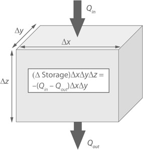
Fig. 8.1 Water balance for a soil volume with the fluxes \(Q_{in}\) entering the volume and \(Q_{out}\)S exiting the volume. (https://www.cambridge.org/core/books/climate-change-and-terrestrial-ecosystem-modeling/soil-moisture/94367F1E2A95F1B991C333BB0637409C)#
The water content of unsaturated soil surface layer (also termed vadose zone, see Section 6) is a particularly important determinant of land–atmosphere coupling. A dry surface layer develops in the absence of rainfall, and this dry layer impedes soil evaporation. Conversely, plant roots can extend deep in the soil to sustain transpiration during dry periods. Below the vadose zone lies saturated groundwater, and soil moisture also controls the fluxes of water between the vadose zone and groundwater (Fig. 8.2).
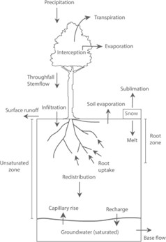
Fig. 8.2 Water flows in a soil column extending from the ground surface to the water table. (https://www.cambridge.org/core/books/climate-change-and-terrestrial-ecosystem-modeling/soil-moisture/94367F1E2A95F1B991C333BB0637409C)#
The scheme of water balance implemented in the FeST model is articulated in three cases, according to whether the cell is located on hillslope, on a land plain where aquifer takes place, or in a lake.
8.1. Cell on hillslope#
Cell on hillslope is supposed to be divided in two layers: the root zone where vegetation roots develop and water can be exchanged with atmosphere, the transmission zone where water can be stored as perched water table and migrate downward (Fig. 8.3).
Water balance for root zone and transmission zone, for unit area, is computed as:
where \(\vartheta_{t + 1}^{rz}\), \(\vartheta_{t + 1}^{tz}\), \(\vartheta_{t}^{rz}\), and \(\vartheta_{t}^{tz}\) are root and transmission zone soil moisture at time \(t + 1\), and \(t\), respectively; \(I\) infiltration (m/s) (see Chapter 6); \(ET\) actual evapotranspiration (m/s) (see Chapter 7); \(P\) is the percolation from root zone computed as actual hydraulic conductivity Equation (6.2); \(DP\) is the percolation out of transmission zone, computed as hydraulic conductivity at saturation, multiplied by a coefficient that accounts for the degree of bedrock fracturation (0 for impermeable bedrock, 1 for fully permeable bedrock); \(TSE\) and \(RSE\) are saturation excess from transmission and root zone, respectively; \(RZD\) and \(TZD\) are root and transmission zone depth (m), respectively; \(\mathrm{\Delta}t\) is time step duration from \(t\) to \(t + 1\). \(RSE\) is summed to runoff to account for the saturation excess runoff formation mechanism. \({LF}_{out}\) is the lateral subsurface intercell flux. It is assumed that saturated subsurface flow in soils along the hillslope profile is described by Darcy’s law (Swenson et al., 2019). Volumetric discharge in m³/s is computed as:
where \(w\) is the cell width (m), \(D_{s}\) is the thickness of the saturated zone (m), \(i\) is the topographic gradient (m/m) assuming a kinematic wave approximation. \(\overline{{\ K}_{sub\ }}\) is the subsurface soil hydraulic conductivity at saturation computed as the harmonic mean between the values of the current, \({\ K}_{sub\ }\), and downstream cell, \({\ K}_{sub,d\ }\):
\({LF}_{out}\) becomes \({LF}_{in}\) for the downstream cell following the topological cell interconnections defined for surface routing.
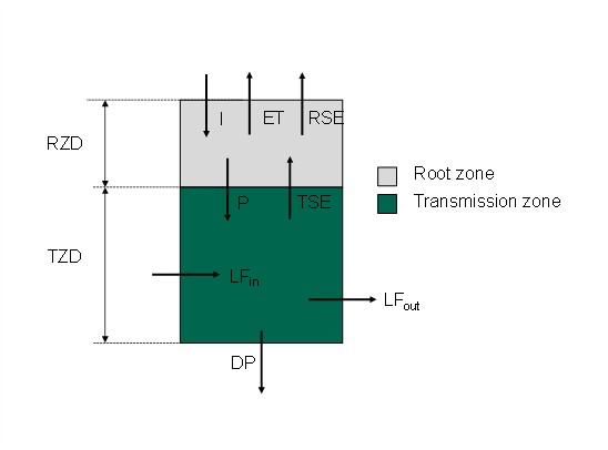
Fig. 8.3 Soil balance scheme of cell on hillslope. RZD = root zone depth, TZD = transmission zone depth, I = infiltration, ET = evapotranspiration, RSE = saturation excess from root zone, P = percolation, TSE = saturation excess from transmission zone, \(LF_{in}\) = input lateral flux, \(LF_{out}\) = output lateral flux, DP = deep percolation.#
8.2. Cell in land plain#
This cell type characterizes the land plain area where vertical fluxes are dominant respect to lateral ones due to the mild or absent topographic slope. When land plain cell lays on top of aquifer, the deep percolation contributes to groundwater recharge. A vertical flux from the bottom is assumed in the opposite direction due to capillary rise from saturated soil. Capillary flux reduces groundwater recharge and is included as inlet to root zone balance. (Fig. 8.4).
Water balance for root zone and transmission zone, for unit area, is computed as:
where \(\vartheta_{t + 1}^{rz}\), \(\vartheta_{t + 1}^{tz}\), \(\vartheta_{t}^{rz}\), and \(\vartheta_{t}^{tz}\) are root and transmission zone soil moisture at time \(t + 1\), and \(t\), respectively; \(I\) infiltration (m/s) (see Chapter 6); \(ET\) actual evapotranspiration (m/s) (see Section 7); \(P\) is the percolation from root zone computed as actual hydraulic conductivity (Equation (6.2)); \(DP\) is the percolation out of transmission zone, computed as hydraulic conductivity at saturation, multiplied by a coefficient that accounts for the degree of bedrock fracturation (0 for impermeable bedrock, 1 for fully permeable bedrock); \(CR\) is capillary rise flux; \(TSE\) and \(RSE\) are saturation excess from transmission and root zone, respectively; \(RZD\) and \(TZD\) are root and transmission zone depth (m), respectively; \(\mathrm{\Delta}t\) is time step duration from \(t\) to \(t + 1\). \(RSE\) is summed to runoff to account for the saturation excess runoff formation mechanism.
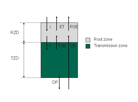
Fig. 8.4 Soil balance scheme of cell in land plain. RZD = root zone depth, TZD = transmission zone depth, I = infiltration, ET = evapotranspiration, RSE = saturation excess from root zone, P = percolation, TSE = saturation excess from transmission zone, CR = capillary rise flux, DP = deep percolation#
Capillary rise flux is assumed to come from the saturated soil of the underlying groundwater and reaching the root zone. It is computed with Darcy law according to the following equation:
where \(\overline{K}\) is the hydraulic conductivity (m/s) at the interface with groundwater table computed as the harmonic mean between the saturated conductivity, \(K_{s}\), and the unsaturated conductivity of root zone, \(K_{rz}\):
\(\psi_{rz}\) is root zone soil suction (m) computed from Equation (6.1)) according to the root zone actual soil water content; \(d\) is the water table depth (m). When water table depth lies within the root zone or it is above ground elevation, root zone and transmission zone are assumed to reach soil saturation, vertical fluxes are set to zero except capillary rise that is set equal to potential evapotranspiration rate (this becomes a negative source term for groundwater head update), and runoff that is set equal to rainfall rate.
8.3. Cell in a lake#
Cell in a lake is subjected to a simplified balance: soil water content is set to saturation, evapotranspiration is set to potential value, runoff is computed as precipitation less evapotranspiration rates.